![[Warning]](images/community/docbook/warning.png) |
Warning |
|---|---|
|
The Object handling menu is no longer supported in the 2021 version of Geoconcept Web. However it remains available on condition that it is re-enabled by setting the easy.objectManagement.hideMenu to false. The correct functioning of all the elements described in this chapter is no longer guaranteed. |
This tab enables creation and handling of vector object display in the interactive map, by saving data in the application’s database.
It handles:
- creating categories: a category contains different types of objects. The name of the categories will appear at the top of the cartographic application in the form of drop-down menus,
- creating types of objects: these objects may be point, line or area type objects,
- creating objects: each object belongs to an object Class. The interface allows the user to enter the geometry of these objects manually, and to assign values for the attributes, in the limits of the fields suggested. These attributes will be stored in the application’s database
- importing vector objects: from a text file containing the data, the import tool enables insertion in the database of the records contained in the text file,
- an option to validate modifications: any object modified by a contributor is saved in the temporary table. A validation of this modification will enable it to be saved in the production table,
- positions: as seen in the Designer, when a map is selected, the positions on the Geoconcept map are retrieved so they can be used in the web application. This tool allows the user to create and save a new position independently of the Geoconcept map, useable only in the web application,
- stored queries: it is possible to create queries on the point objects stored in the database. The queries will interrogate the attributes of objects via the equals operator. The syntax and the list of fields that can be interrogated will be described in the sections that follow.

The menus used to create a category, an object Class, a position or a stored query operate identically: there is an Add button that opens an interface in which the parameters specific to each menu can be defined.
The category serves to classify the different vector object Classes. A natural way to classify may be to structure thematically, but this is only one example of how to classify, and can be adapted to each type of project and requirements generally.
The category can regroup object Classes of different types, whether these are points, lines or polygons, as the example below shows.
The category acts like a drop-down menu that it is possible to view when you pass over the category with the mouse. The list of object Classes associated to this category then appears.

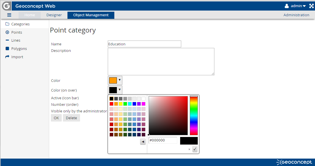
The creation of a category must take place via the web interface. It is created using the Add button available in this interface. This button allows the user to open a form containing the following configuration fields:
- name: this is essential, and is used in the user interface as well as being the name displayed in the menu,
- the description: optional, this is displayed only in the category handling interface, for the benefit of connected users,
- Colour and flyover colour: these are optional. If the HTML colour code has not been assigned, its colour by default in the user interface is blue with the following code: #005AA1. The colour can be assigned by typing the hexadecimal code directly or by using the tools available (colour palette, RGB fields). Clicking on the green arrow to the side of each colour check-box assigns the chosen colour,
- Active: this option is checked by default and allows the category to appear in the user interface. Unchecking this check-box effectively masks the category in the mapping interface (and so masks all the object Classes and objects belonging to this category), including that of the administrator.
- Number: this number is used to classify the order in which the categories are sorted: in the example above, Category 2 is classified number 1, while Category 1 is classified as number 2, explaining the reverse order in their display. By default, the value zero is assigned to the categories, their ordering is then defined by the order of creation,
- Visible only by the administrator: when activated, this option masks the category (and all that it contains) to users of the mapping application. Only the administrator, connected as such via the backoffice interface, can see this category. This check-box is unchecked by default, when the category is created.
![[Tip]](images/community/docbook/tip.png) |
Tip |
|---|---|
|
The categories created are saved in the table in the database called gw_city_site_category. |
Click on OK to validate the parameter settings made and save them in the database. This new category will appear in the form of a line in the category menu of the Object management interface and in the form of a menu, empty for the moment, in the user interface.
To delete a category, it will be necessary to click on the corresponding line in the backoffice interface, and then to click on the Delete button.
It is not possible to delete a category if it still contains any object Classes.
As we have seen elsewhere, there are three types of object Class that can be created in the web application: point, line or polygon.
Creating an object Class is the same procedure every time: click on the Add button to open an interface in which it will be necessary to define the display parameters for all the objects in the Class in question.
|
Warning |
|---|---|
|
We recommend first creating a category of objects, then a Class of objects, and finally an object. In effect, if an object is created without being assigned to a Class, this Class itself being assigned to a category, it will be invisible for users of the mapping application. |
Each Class of object may ultimately be assigned to a group of users: in this case, only the users in the defined groups will be able to see the objects of this Class.
The point Class (or points)
In this Class, objects with X,Y coordinates can be saved and represented by a symbol or an image.
The list of point object Classes saved in the application appears in the interface. It reads and displays certain saved parameters.

To modify the parameters saved for a Class, click on the name of the Class to display the form. Once the parameters have been modified, save the changes by clicking on OK. Conversely, click on Delete to delete the Class.
|
Warning |
|---|---|
|
This deletion is only possible if there are no objects in this Class. |
In the form of a point Class, the following fields should be assigned values:
- Name: this is mandatory, and enables display in the drop-down menu of the Class name,
- Category: mandatory. By default, a category is assigned. The user is invited to choose the category among those the user has created via the drop-down menu. The point object Class will then be stored in the category chosen in the user interface,
- Description: optional,
- Group: optional. If one or more groups is defined here, the users of these groups will be able to see the objects. The other users will not have this option.
- Image: for the 12 preset map scales in Geoconcept retrieved in the web application, it will be necessary to define a display of objects by Class of points. So the administrator can choose an icon within the database of images via the drop-down menu that is suggested to the administrator. For more details about the database of saved images in the application, please refer to la Section Images,
- Active: by default checked, this check-box displays the point Class in the mapping interface. Unchecked, nobody will see this Class and the objects associated to it,
- Visible exclusively by the administrator: unchecked by default, this check-box can restrict the display of this Class and its associated objects in the mapping interface to the administrator connected with their own identifiers. This utilisation can, for example, be deployed by an administrator wishing to prepare and refine data before publishing them.
- Number: this allows the user to classify the Classes of points belonging to a single category. By default, the value is zero and the display order follows the order of creation,
- Minimum and maximum scale: from 1 (min) to 12 (max), these scales limit the display of objects to a scale falling within the range indicated,
- Class, Subclass, Fieldnames (Geoconcept) and Max distance are notions that will be explained in the section called “Additional attributes”.
Clicking on OK allows the user to save the parameters for the Class.
Note: Classes of points are saved in the database table called: gw_city_site_type. A unique identifier is created for each Class of points. This identifier is important when integrating data directly in the database. This subject will be revisited in a separate section of the documentation: Connecting the database to a Geoconcept map.
|
Tip |
|---|---|
|
When creating a point Class, no image is saved for the preset scales. If the administrator wants to assign the same image to the 12 preset scales of the web application: selecting just the image for scale 12, then clicking on OK, the same image is saved for all the preset scales. This manipulation is no longer possible once an image has been assigned for each preset scale. |

Line Class
Saved lines will be stored in this Class. The parameters enable definition of the display of the line in the web interface.
Use the same procedure to create a line Class as for a point Class, using the Add button. The parameters to configure correspond to the display parameters for a line.
The parameters available are the following:
- Name: mandatory, this is the name that will display in the user interface,
- Category: mandatory, this enables classification of the Class in question in a category,
- Description: optional, this appears in the list of line Classes,
- Group: optional. If one or more groups is defined here, the users of these groups will be able to see the objects. The other users will not have this option.
- Colour: optional, this colour parameter allows definition of the colour of the line. By default, the colour is black. This colour can be specified via the colour palette or the RGB fields to be filled,
- Active: the check-box is checked by default to enable display of the Class in the interface. Unchecked, the Class and its objects do not appear in the interface,
- Visible only by the administrator: the check-box is unchecked by default. When it is activated, only the administrator connected to the backoffice can see this Class and its objects in the user interface,
- Number: this defines the order in which the lines in a same category will display,
- Width and opacity: in pixels, these display parameters for all line objects belong to the Class,
- Display direction: unchecked by default, this option displays the arrows showing the direction of capture for the line on the object,
- Minimum and maximum scales: from 1 (min) to 12 (max) these enable restriction of the display of objects to the range of scales defined by minimum and maximum,
- Class, Subclass, Name of fields (Geoconcept) and Max Distances are notions that will be explained in the section called “Additional attributes”.
Clicking on OK allows the user to save the parameters for the Class.
|
Tip |
|---|---|
|
The point object Classes are saved in the database table called gw_city_route_type. A unique identifier is created for each type of line. This identifier is important when integrating data directly in the database. |

The polygon Class
In this Class, simple polygons are saved. The parameters enable definition of the display of all the polygons in the Class in the web interface.
To create a polygon object Class, follow the same procedure as for a point Class, using the Add button. The parameters that need to be assigned values correspond to the display parameters for a line.
The parameters available are the following:
- Name: mandatory, this is the name that will display in the user interface,
- Category: mandatory, this enables classification of the Class in question in a category,
- Description: optional, this appears in the list of polygon Classes
- Group: optional. If one or more groups is defined here, the users of these groups will be able to see the objects. The other users will not have this option.
- Colour and border colour: optional, these parameters enable definition of the polygon colour. By default, the colour is black. This colour can be specified via the colour palette or the RGB fields to be filled,
- Active: by default this is checked to enable display of the Class in the interface. If it is unchecked, the Class and its objects do not appear in the interface,
- Visible exclusively by the administrator: unchecked by default. When activated, only the administrator connected to the backoffice can see this Class and its objects in the user interface,
- Number: this enables definition of the order in which the polygon Classes will be displayed in a single category,
- Width and opacity: in pixels these are the display parameters for all polygons belonging to the Class,
- Minimum and Maximum scales: from 1 (min) to 12 (max), they limit the display of objects to a scale falling within this range,
- Class, Subclass, Name of the fields (Geoconcept) and Max Distance are notions that will be explained in the section called “Additional attributes”.
Clicking on OK allows the user to save the parameters for the Class.
Note: the point object Classes are saved in the database table called gw_city_polygon_type. A unique identifier is created for each polygon Class. This identifier is important when integrating data directly in the database.

This section explains how to create an object manually via the intermediary of the web interface and its associated forms.
For each object that can be created, whether a point, line, or polygon, the procedure is the same. The administrator (or contributor) connected must click on Add to create a new object. The interface shows the fields to fill on the left, and on the right, a map in which the geometry of the object can be captured manually.
|
Warning |
|---|---|
|
It is essential to create a category and a Class before creating the objects. |
Adding a point object
The form for creating a point object includes the following fields:
- Name: mandatory: this allows the user to assign a name to the point created,
- Class: mandatory: this makes it possible to associate the point to a Class, ad so to a pre-defined appearance. The display of all points within one Class follows a click on the name in the drop-down list in the user interface. The Class does not appear in the infobox,
- Description: optional, allows the user to input text,
- Contact: optional, the name of the person for whom the contact details are specified,
- Telephone and fax: optional: the numbers appear associated to a representative icon,
- Email: optional: this parameter allows specification of the contact email address,
- URL: optional: the web URL enabling a page to be opened in another tab in the browser. The URL must start with http://,
- Address, post code, and town: these information items are optional, and if assigned values will appear in the infobox. They may serve for positioning the point on the map via the geocoding module using the Geocode button,
- image or Image path (local): optional, this allows addition of an image to the infobox. This image can be stored in the images database, or directly on the server. It is therefore necessary to supply an access path to the image,
- PDF file: optional, this option provides a link in the infobox to open a PDF file stored on the server,
- Video link and video title: optional, this sets up a link to an Internet page external to the application. The name appearing in the field called video is the name that appears in the infobox,
- Publication start and end dates: optional, the point object will only appear in the mapping interface if the current date is included in the dates supplied. If no date has been supplied, the object will always be displayed without any condition on the date.
All the fields filled in the form with values will appear in the infobox, except for the Class, the external reference, the publication start and end dates and the source of the information. The fieldname of an unfilled field will not appear in the infobox.


The point objects created via the web interface are saved in the table called gw_city_site.
Objects stored in this table are only visible by a user connected also to the application backoffice, so long as the objects have not been validated.
|
Tip |
|---|---|
|
In a web site accessible to the wider public, an administrator can choose to add objects. So long as they have not validated the display of objects in the mapping interface, the objects are not validated. This means the public will not see these objects. |
Adding a line object
The form for creating a line object includes the following fields:
- Name: mandatory, this enables a name to be given to the line created,
- Class: mandatory, this serves to associate the line to a Class and therefore to a pre-defined appearance. The display of all the lines in a same Class occurs when the name in the drop-down list in the user interface is clicked on. The Class does not appear in the infobox,
- Distance / Duration: optional, these options serve to define a distance and a duration assigned to the line,
- Description: optional, allows the user to input text,
- URL: a web URL that opens the page in another browser tab. The URL must start by http://,
- image or Image path (local): optional, this allows addition of an image to the infobox. This image can be stored in the images database, or directly on the server. It is therefore necessary to supply an access path to the image,
- PDF file: optional, this option provides a link in the infobox to open a PDF file stored on the server,
- Zip URL: optional, this allows a link to a URL to be stored so a file available on an Internet site can be downloaded;
- The Capture and Reverse buttons: inputting in the map using the mouse and the Capture buttons is mandatory. The Reverse button reverses the direction of capture for the line, visible thanks to the arrows. A double-click in the map allows capture of the points on the line object.
All the fields filled in the form will appear in the infobox, except the Class and the publication start and end dates, the external reference and the information source. The fieldname of an unfilled field will not appear in the infobox.


The line objects created via the web interface are saved in the gw_city_route table.
Objects stored in this table are only visible by a user connected also to the application backoffice, so long as the objects have not been validated.
Adding a polygon object
The form for creating a polygon object includes the following fields:
- Name: mandatory, this enables a name to be given to the polygon created,
- Class: mandatory, this enables the polygon object to be associated to a Class and therefore to an appearance defined previously. The display of all the polygons in the same Class is achieved by clicking on the name in the drop-down list in the user interface. The Class does not appear in the infobox,
- Polygon: optional, this option enables definition of an area assigned to the polygon,
- Description: optional, allows the user to input text,
- URL: a web URL that opens the page in another tab of the browser. The URL must start with the HTTP protocol,
- image or Image path (local): optional, this allows addition of an image to the infobox. This image can be stored in the images database, or directly on the server. It is therefore necessary to supply an access path to the image,
- PDF file: this option provides a link in the infobox that opens a PDF file stored on the server,
- Zip URL: optional, this allows a link to a URL to be stored so a file available on an Internet site can be downloaded;
- The Capture button; capture in the map using the mouse and the Draw polygon button is mandatory. The new version creates a hole in the polygon using the CTRL button on the keyboard. It is also possible to modify the polygon using the Modify a polygon button. Activating this option, it is possible to modify the edges of the polygon by moving the circles displayed.
All the fields filled in the form will appear in the infobox, except for the Class, the external reference, and the information source. The title of an unfilled field will not appear in the infobox.


The vector objects displayed in the mapping interface by all current users with access to the application are those stored in:
- the gw_city_site_prod table for points;
- the gw_city_route_prod table for lines;
- the gw_city_polygon_prod table for polygons.
The Validate modifications menus (available for points, lines and polygons) enable data to be copied from the gw_city_site, gw_city_route and gw_city_polygon tables into gw_city_site_prod, gw_city_route_prod and gw_city_polygon_prod respectively.
These allow the user to compare two tables (for example gw_city_site and gw_city_site_prod in the case of point objects) and to highlight the differences.
The aim is to always dispose of the same records in both tables, while maintaining the possibility of publishing the modifications in differed time, at the discretion of the administrator.
In this way, in order to “switch on” a modification on an object captured by a contributor to make it visible to everyone in the mapping application, it will be necessary to proceed via the Validate modifications menu.

This illustration shows how the administrator, or a contributor:
- has added a point called POI4: this point is present in the gw_city_site table, and is therefore visible only by the administrator or a contributor in the mapping portal. Click on Add this point in production to copy the record into the gw_city_site_prod table. The POI4 object then becomes visible to everyone. A click on the Cancel the addition of this point deletes the object in the gw_city_site table, without copying it into the gw_city_site_prod table.
- has modified the point POI1: the administrator has modified the attributes or its geographic position. The administrator or contributor views their modifications in the mapping interface, while the public user views the non-modified object. A click on the Update this point in production publishes modifications made to all users by copying the modifications into the gw_city_site_prod table. A click on the Cancel the modification of this point restores the status of the record in the gw_city_site table.
- has deleted the point PO13. The administrator or contributor no longer sees this object in the mapping interface, while the public at large still sees it. A click on Delete this point in production deletes it also from the gw_city_site_prod table, that is, for everyone. This action is irreversible. A click on the Cancel deletion of this point button restores the status of the record in the gw_city_site table by copying the object from the gw_city_site_prod table.
The Add / Update / Delete all these points in production functions serve to apply the action in question to all the objects under consideration.
The platform offers the option to import vector data in bulk via the Import objects menu. This allows data import from a text file that must respect a format in order to respect in turn the requirements of the interface to fill the corresponding fields.
This menu enables import of point, line, or polygon objects. The selection is made via the Type of object drop-down list.
Importing point objects
You need to choose the .txt file to import, the POI Class in the Type of object list. it is then necessary to choose the field separator, the field delimiter if present, the number of lines to ignore (header lines) and finally the character set.
This importation will allow completion of the gw_city_site table.

You will need to respect the precise structure as expected by the application. The text file must then dispose of 21 fields, even if these happen to be empty. The only non-empty field, that it is mandatory to complete, is the Class field (field 14: this is the name of the point object Class in which the new imported objects will be stored. The field must bear exactly the same name as the Class to which it must belong.
The extRef field (field 1) is the key field that can be used when updating data. In the gw_city_site table, this will be the EXTREF field.
Below is an example of a text file that can be imported into the application via this menu, in order to update two objects in the TypePonctuel1 Class:

The result of the import is as follows:

The two new point objects have been imported into the gw_city_site table and are therefore visible by the administrator in the mapping application and in the object management interface.
A new import with the following file will give the results below:


Importing line objects
The Object import menu imports line objects from a text file. It will be necessary first to select in the drop-down list the Class of objects by choosing Line. This import enables completion of the gw_city_route table.
With immediate effect, the fields to be assigned values for an object of this class will change:

The fields that can be filled are the same as those available in the input form of a line object.
The mandatory field is the Class field (field 6) that must have the same name as an existing line object Class. The extRef field (field 1) serves as a key when updating a record.
Field 5 is the object Geometry field: the geometry must be saved in WKT format to be integrated in the application.
|
Tip |
|---|---|
|
The WKT field is a field format provided by Geoconcept for exporting object geometry in a text format. |
Here is an example of a text file that enables integration of a Line2 object in the TypeLine1 line object Class.

The following image shows the result: the Line2 object has been integrated in the TypeLine1 Class.
Updating data is achieved via the extRef field; this update will appear in the Updated central group.
If the line object Class is not present, or is not recognised, the object will not be added to the gw_city_route table and an error message will appear in the Ignored group.

Importing polygon objects
The Object import menu enables import of polygon objects from a text file. To do this, it is necessary in the first place to select in the drop-down list the object Class by selecting Polygon. This import will enable you to complete the gw_city_polygon table.
With immediate effect, the fields to be assigned values for an object of this class will change:

The fields that can be filled are the same as those available in the input form for a polygon object.
The mandatory field is the tupe field (field 6), that must have exactly the same name as an existing polygon object Class. the extRef field (field 1) serves as a key when updating a record.
Field 5 is the geometry field for the object: the geometry must be saved in WKT format to be integrated within the application.
|
Tip |
|---|---|
|
The WKT field is a field format provided by Geoconcept for exporting object geometry in a text format. |
Here is an example of a text file that allows integration of a Surface2 object in the TypePolygon1 polygon object Class.

The following image shows the result: the Surface2 object has been integrated in the TypePolygon1 Class.
Updating data is achieved via the extRef field; this update will appear in the Updated central group.
If the polygon object Class is not present, or is not recognised, the object will not be added to the gw_city_polygon table, and an error message will appear in the Ignored group.

Conserve on import of objects
The objects can be added to the web application by an import of a text file containing the attributed and geometric data on objects. This manipulation can be performed remotely without accessing the server where the application and the database are stored.
The name of the Class in which the objects must be imported is given in the object menus without any need to know their identifier in the database.
This manipulation is therefore open to all users who have the right to access the backoffice. It should, nevertheless, be remembered that to add objects via this menu enables them to be added to the gw_city_site, gw_city_route, and gw_city_polygon tables. To switch them into production and make them visible to all users of the mapping application, it will be necessary to validate them using the object validation menus.
|
Warning |
|---|---|
|
The coordinates system in which the object geometry is written (X Y for points, WktGeometry for line and polygon objects) must be the same as that of the web application map. |
The vector objects in the web application are stored in the database with a restricted number of attributed fields, The administrator has the possibility of specifying additional attributes for vector objects. These attributes are stored in the objects on the Geoconcept map and are retrieved by the web application.
To call these additional fields, it will be necessary for the administrator / contributor to know the exact name of the Class in Geoconcept, along with the exact Subclass and field names.
The specification is performed during the configuration of the Class of vector objects. In the cases of the three different point object types, the text boxes provided need to be filled:
- Class (Geoconcept),
- Subclass (Geoconcept),
- Field names (Geoconcept),
- Max distance (in pixels),
By filling in these fields, the vector object stored in the web application database is virtually linked to the Geoconcept object (that belongs to the Class and Subclass as specified) by its geographic position within a radius of the maximum distance specified. This link is only valid between the web application and the Geoconcept map via a query that allows a return of attributed information on an object by specifying the Class, the Subclass, the name of the fields and the maximum distance around the object in question.
In concrete terms, when the user clicks on a vector object in the web application, its X and Y coordinates are sent to the Geoconcept map, that in turn interrogates the objects in the specified Class / Subclass within a radius of the specified distance,
It is therefore necessary that the object saved in the gw_city_site table is located at the same coordinates as its twin object in the Geoconcept map. This is clearly the case if the objects in the web application originate from an export from the Geoconcept map.

To access these additional attributes: it is necessary to supply exact information regarding the Geoconcept Class, the Subclass, and the names of the fields that will be displayed in the infobox.

This means that in the mapping application, a click on the point will open the additional infobox for the fields sourced by the Geoconcept map. The name of the additional fields is the name specified in the Geoconcept map.

We need to check that these fields, not stored in the database, are filled by the information derived from the Geoconcept map object.
|
Warning |
|---|---|
|
These additional fields are sourced by the Geoconcept map via a query sent by Geoconcept Web. They cannot, under any circumstances, be interrogated by the configured query tool. |
It is possible to add icons, images, or symbols (in addition to the configurable image in the infobox) to the infobox of vector objects: these will be placed in the lower part of the infobox.
To add this symbol to the infobox, the symbol must be saved in Geoconcept Web’s images database.
In the Object manager / Points tab, a Symbols menu allows you to add a symbol, that is, to choose one (or two) images that correspond to this symbol. The images can then be chosen in the databank of images in the Designer.
The symbol is configured in this way. The display of symbols is achieved at the level of each object. As soon as a symbol has been configured, it will be possible to choose it in the attributes of each object, in the lower section of the attributes. By default, no defined symbol is selected. By clicking on the icon (in the case where the symbol only contains one image) or on one of the two icons (in the case where the symbol is defined with two images), you select the image that will appear in the infobox. To delete it from the infobox display, you will need to click again on the corresponding icon.
In order to update the vector data present in the mapping application and so stored in the Geoconcept Web database, it is possible to configure links between the Geoconcept map and the database.
This section is not designed to replace the Geoconcept reference guide in relation to the setting up of such links, but to adapt their implementation in the special case of the Geoconcept Web database.
When importing objects from a Geoconcept map and the Geoconcept Web database, the constraints of fields in objects in the Designer must be respected. In this way, a Class must absolutely be associated to each object imported into the Geoconcept map in the database (the value of the Class is visible in the gw_city_site_type table, for point objects for example). In addition, the geocode_score and geocode_type fields of point objects must not be null: a value of zero must in this way be assigned to them by default.
Note also, that in the case of line or polygon objects, the geometry of the WktGeometry field respectively in the gw_city_route (gw_city_route_prod) and gw_city_polygon (gw_city_polygon_prod) tables must be written in WKT format, available when exporting from Geoconcept.
|
Tip |
|---|---|
|
This section is aimed at expert users. |
Line or polygon objects with a complex geometry can be simplified in order to optimise their display in the web application, in the case of a very large number of objects and points on each object. This simplification is automatically applied by the application between a scale of 12 and the scale specified in the parameters. A field called wktGeometrySimplified is present in the database in the tables related to the objects, and is filled during the first display of the object in question (line or polygon).
The administrator can configure the minimum scale up to and including which objects must be geometrically simplified.
|
Warning |
|---|---|
|
When installing the application, these parameters do not exist. They are created the first time that a line or polygon is displayed. |
|
Tip |
|---|---|
|
Here are the parameters to create if you want to do this manually:
|
|
Tip |
|---|---|
|
Once the WktGeometrySimplified field has been automatically filled by the application, this field is no longer modified by the application, even if the parameters are modified by the administrator. To force the application to simplify the geometry again while taking into account the new parameters, it will be necessary to manually delete the field values for WktGeometrySimplified in the database for the objects in question. Next, display the objects in the mapping portal to enable recalculation of the simplified geometry values. |
It is possible to restrict access to the different types of vector objects by associating them to one or several groups. This configuration is applied in the page handling vector object types, for points, lines or polygons.

This means that a user who can see the Object list widget will only see objects of the Point1 type if they belong to group1. If the user does not belong to this group, they will not see these objects. The other selection or query widgets will also exclude this object Class when a search is performed.
