SmartRouting is a powerful route calculation and proximity search engine. Route calculations are based on a file describing the road network, referred to as a graph. This file is created from the Geoconcept GIS and a route navigation database, such as that published by Navteq. A series of speed profiles can be defined (pedestrian, heavy goods vehicle, etc) and various traffic circulation rules taken into account (no-entry, one-way street, no U-Turns, etc). SmartRouting Server can perform various operations:
- calculation of an itinerary between two points,
- calculation of an itinerary between one point and several points,
- creation of a route sheet,
- search for entities in proximity to a reference point (Search Around).
SmartRouting can be used to obtain a complete itinerary along with the description of the route (including the path the route follows between two intersections), the duration of the journey between each segment and the distance.
This documentation describes this component, and is in two distinct parts:
- SmartRouting JEE : this is a component designed for the integration of the SmartRouting route calculation engine within the Java Enterprise Edition (JEE) platform and its sub-assemblies such as the Tomcat servlet engine.
- SmartRouting Command line : this is a component designed to calculate itineraries from the command line.
The Graph: any calculation function requiring a graph trajectory requires the utilisation of a graph. The graph constitutes a logical view of the network. It contains and describes all information related to the connectivities between road sections, to the costs and constraints. It is constructed and organised in such a way that the calculations are applied efficiently. The file is in SITI format.
![[Tip]](images/community/docbook/tip.png) |
Tip |
|---|---|
|
This SITI format corresponds to the second generation of graphs developed for Geoconcept (from version 6.5 of Geoconcept onwards). It potentially integrates numerous additional characteristics (multiple speed profiles, numerous management rules…). |
Please refer to the Geoconcept Solution Reference Guide for details of the rules that apply when creating a graph.
When making calculations, the start points, stops and finish points are linked to the network constituted by the graph, even if the objects are distant from it (points situated at a certain distance from the network): this is the snap-to-graph function. This operation aims to search around these points for the closest road sections. Then, these road sections are used to determine the start points of possible solutions.
The itinerary as calculated then integrates a distance covered between these points and the graph, called the snap-to-graph distance. To optimise performances, there is an option that allows a maximum snap-to-graph distance to be set in metres (max graph snap distance). This rules out any need to browse the whole of the network to find the nearest road sections.
In addition, the snap-to-graph speed, the speed of traversing the distance separating the start, stop or finish points can also be customised (graph snap speed).
A metagraph consists of the possibility of integrating within the creation of the graph a simplified graph, or a graph that is only a subset of its original content. The utilisation of the metagraph aims, essentially, to accelerate the traversing of the graph, when performing route calculations over long distances.
![[Note]](images/community/docbook/note.png) |
Note |
|---|---|
|
If an itinerary must be calculated between two distant towns several hundred kilometres apart, it is preferable to give precedence to a graph trajectory at the level of the main routes (tending towards logic level 1, for example, that is considered as the highest level of thoroughfare). Around the start points, and any stop or finish points, the logic levels that are not present in the metagraph will still be employed, but for inter-town links the logic levels used in the metagraph take precedence. |
The metagraph is a file accompanying the SITI graph. It is made up of the association of a file in MG format and an MGLIST file. The MG file is loaded into memory.
This is the logic level on which the route calculation will principally be performed. Two scenarios are possible:
- using a metagraph: this is the “normal” scenario, the metagraph being specifically constructed to accelerate the calculation of the itineraries over long distances (only the larger roads will be selected on longer journeys). It is necessary to assign values to the logic level defined in the metagraph in order to optimise calculation times,
- when not using a metagraph: the route calculation will be optimised by interrogating as a priority the road sections at the level specified directly in the graph.
![[Warning]](images/community/docbook/warning.png) |
Warning |
|---|---|
|
Around way points (for example, start, stop and finish points) all routes will be taken into account, whatever logic level has been selected. |
|
Warning |
|---|---|
|
A logic level that is set too high can adversely affect the quality of the route calculation since numerous routes will not be taken into account. |
JEE Integration
JEE SmartRouting is a component for integrating within a JEE platform, and offers a route calculation service to JEE modules deployed on an applications server (in the widest sense, including a Tomcat type of servlet engine).
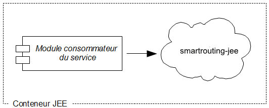
The consumer module can be of any type (webapp, ejb, etc). Even inside the JEE module, the consumer can be of any type (servlet, jsp, pojo, etc).
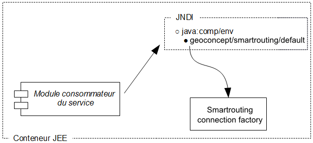
Method of access
The application using the route calculation facility references the provider via a logical name from the JNDI directory (Java Naming and Directory interface) for the application server. The method for setting up a provider will be described later on.
Traditionally, the logical name used is “geoconcept/smartrouting/default” from the “java:comp/env” context, but it is possible to use another name, another context, or to set up several providers of different types.
In the interests of simplicity, the case of the most common utilisation (a single local primary provider with a default naming system) will be described first.
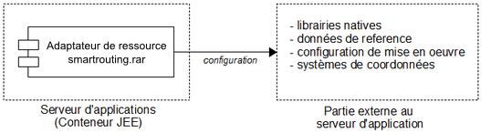
Compoonent structure: Adaptation of the JEE resource and external elements
smartrouting-jee breaks down into several parts. For performances and re-utilisation considerations, the engine (also called the kernel) is written in C++ and is therefore distributed in the form of native libraries. The integration part (resource adaptor) constructs the line with the engine while handling its deployment through the loading of its native libraries. In terms of deployment of files, this therefore concerns two distinct trees:
In terms of execution, the native libraries will be loaded into memory during the processing of the application server instance (or into its partition, if necessary, depending on the model) at start-up. The adaptor part of the resource features a java interface and handles the engine instanced in memory directly via JNI.
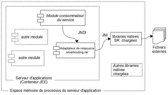
There is no add-on essential to the currect operation of the resource adaptor, so deployment of add-ons is optional.
smartrouting-admin
smartrouting-admin is a webapp for checking the product is correctly installed, and testing the configuration to ensure all is working smoothly.
Configuring the application deployment
A published graph (.siti file) constitutes a data source (datasource).
The service.xml file located in %smartrouting%/conf defines the general configuration of the route calculation service provider. This contains notably a default configuration for the datasources (default‑datasource). You can define a configuration that is specific to a particular datasource. To know what the parameters should be, it is best to consult the hater on options.
If no specific configuration has been defines, the default configuration (default-datasource) will apply to the deployment of this datasource.
In other respects, it will be possible to define some parameters during the call (via CalculateRouteOptions). This means the real value that a parameter takes can be sourced by (in order):
- from the call if it is assigned in CalculateRouteOptions (this assignment is optional)
- from the value indicated at the level of the particular datasource configuration (if a particular datasource configuration has been defined)
-
from the value indicated at the level of the default datasource configuration
default-datasource).
Detailed configuration of a datasource
The configuration of a deployment of a graph can be defined in a very precise way.
This definition can fulfil particular requirements, and is not essential since the default configuration will be perfectly adequate in the majority of cases.
Some parameters can be defined at the time of the call, while others are fixed on creation of the instance of the datasource, and are not modifiable subsequently.
The parameters that one can define also at the time of the all will be described in the CalculateRouteOptions section.
Datasource identification
This section enables identification of a datasource in the administration.
File: graph.
Name: alias of the datasource name (optional).
The options available are those described under the SmartRouting Reference Guide.
These are accessible visually via the smartrouting-admin.war test application, that presents an input for each option in turn so you can observe the behaviour in the result.
Input and output coordinates
If the input coordinates are not in the same coordinates system as the graph, you will have to specify them via the input coordinate system parameter (in the form epsg:4326, for example).
The output coordinates will be in the same coordinates system as the graph, except where the output coordinate system parameter is filled with the EPSG code (in the form epsg:27572 for example).
Output results
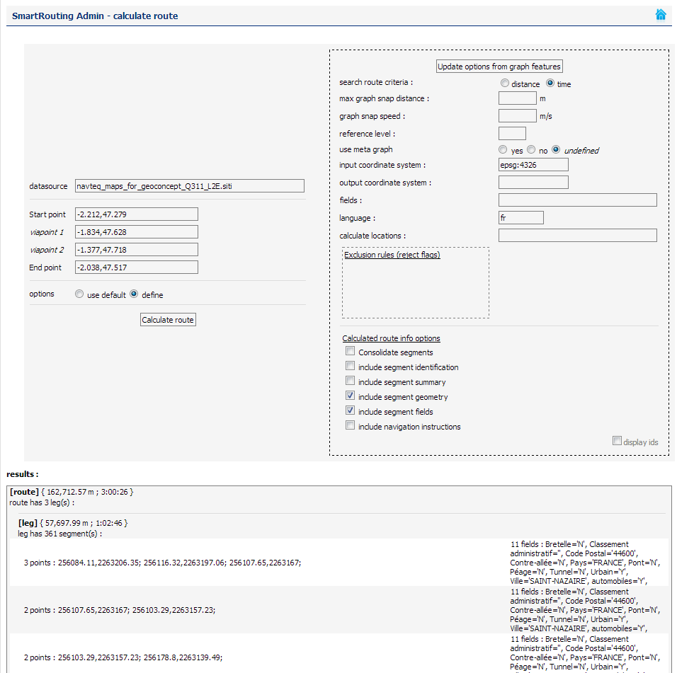
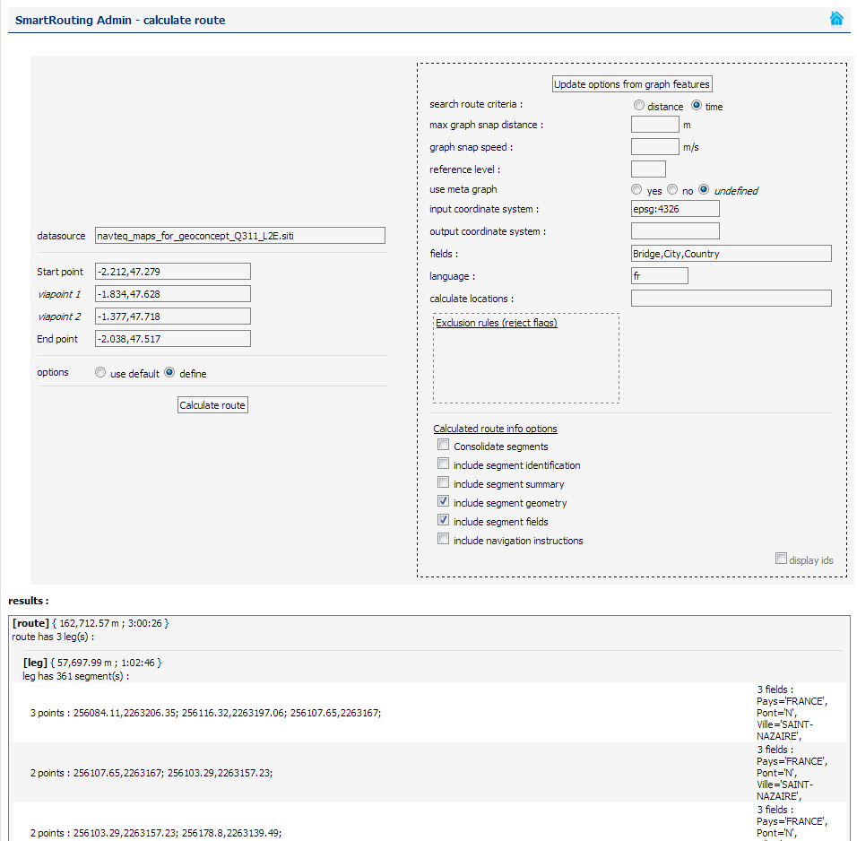
Over and above the component segments of the route calculated, it is possible to receive as a result the attributes of the said segments, thanks to the fields and language fields.
- fields: allows you to select the fields you want to return (by default, all the fields are returned if the option is activated. The name of the fields must be written in English),
- language: allows you to return these fields in the desired language.
Calculate locations
This option allows you to find a point on the calculated route from the start point. The Calculate locations value in seconds allows you to find this point from the start point of the itinerary.
Consolidate segments
This option allows you to regroup, in the result of the route calculation, those segments that will bear the same name and which are close together in a single segment (useful for navigation).
Advanced options
The %smartrouting%/smartrouting/conf/service.xml file allows you to specify the configuration to be used for all graphs.
You will find the configuration for the graphs you currently possess in the Datasources configuration page, by clicking on the info link. The utilisation or not of a metagraph in the graph is displayed at the bottom of the page.
SmartRoutingCommandLine, or SRCmdLine is a standalone application inspired by the principle of UGCCmdLine, that allows calculation of a series of routes in a single operation.
The routes to be calculated are present in an input file (txt):
-
One line per itinerary, with, in the following order:
- X Start
- Y Start
- X Finish
- Y Finish
- TypeDeCalcul(“1” or “Shortest” for a calculation of the shortest route, “2” or “Fastest” for a calculation of the fastest route)
- Each of these values must be separated by a ‘ ;’ character
- The last value, TypeOfCalcul, is optional (if not specified, SRCmdLine takes the value specified in its config: see below)
The results of the route calculations are written to a result file:
-
One line per route, with, in the following order:
- The route length (distance) in metres,
- The route travel time in seconds,
- The route calculation time in milliseconds (the treatment time)
- If it has not been possible to calculate any route, the values will be replaced by “N.A.”.
- Each of these values is separated by a “;”
SRCmdLine is a tool that runs in command line mode from the command line.
- To display the help facility: «SRCmdLine.exe –help»
- To display the product version number: « SRCmdLine.exe –version »
- Where possible, you can specify a series of parameters (some of which are mandatory, and others of which are optional) that will be used to configure SmartRouting, and therefore all route calculations in effect.
- The values of these parameters can EITHER be defined in a configuration file in XML format, OR defined directly in the command line.
- You should specify the config file in the following way: SRCmdLine –config <CheminCompletVersLeFichier>
-
Here is the list of parameters that can be specified:
-
Input file (mandatory):
- Command line; -in <CheminCompletVersLeFichierDEntrée>
- XML: <smartrouting-configuration><smartrouting-input><path>
-
Output file (or results file) (mandatory):
- Command line: -out <CheminCompletVersLeFichierDeSortie>
- XML: <smartrouting-configuration><smartrouting-output><path>
-
Graph (mandatory):
- Command line: -graph <CheminCompletVersLeFichierGraphe>
- XML: <smartrouting-configuration><smartrouting><connection-distance>
-
Maximum search for snap-to distance (optional):
- Command line: -connectionDistance <value>
- XML: <smartrouting-configuration><smartrouting><connection-distance>
-
Snap speed (optional):
- Command line: -connectionSpeed <value>
- XML: <smartrouting-configuration><smartrouting><connection-speed>
-
Reference level (optional):
- Command line: -refLevel <value>
- XML: <smartrouting-configuration><smartrouting><reference-level>
-
Type of route calculation (optional):
- Command line: -itiMode <value>
- XML: <smartrouting-configuration><smartrouting><iti-mode>
- For a shortest calculation: value=1 or value=Shortest
- For a fastest calculation: value=2 or value=Fastest
-
Full loading of the graph (optional):
- Command line: -fullLoadGraph <value>
- XML: <smartrouting-configuration><smartrouting><full-load-graph>
- Full loading: value=1
- Partial loading: value=0
-
Coordinates system as input (optional):
- Command line: -inputProj <codeEPSG>
- XML: <smartrouting-configuration><smartrouting><input-projection>
-
Example of a call to the programme:
-
SRCmdLine -graph "data/graph.siti" -in "data/input.csv" -out "output.csv" -config "config.xml"
- If a parameter is defined both in the config file and in the command line, the value specified in the command line will be taken.
- If the type of route calculation (shortest or fastest) is defined both in the input file and in the config file, or the command line, the value specified in the input file will be the one taken as valid.
<?xml version="1.0" encoding="utf-8"?>
<smartrouting-configuration>
  <!-- Smart Routing configuration -->
  <smartrouting>
    <!-- Graph file path-->
    <!-- <graph-path>E:\SmartRouting-cmdline\SRCmdLine\navteq_maps_for_geoconcept_Q311_france_v2.siti</graph-path> -->
        <graph-path>E:\SmartRouting-cmdline\graphe.siti</graph-path>
    <!-- Mode of routing. 1:Distance, 2:Time -->
    <iti-mode>1</iti-mode>
    <!-- Set connection distance -->
    <connection-distance>150.</connection-distance>
        <full-load-graph>1</full-load-graph>
        <reference-level>3</reference-level>
  </smartrouting>
  <!-- Input configuration (text file format) -->
  <smartrouting-input>
    <!-- Path of the input file. -->
    <path>E:\SmartRouting-cmdline\SRCmdLine\input.csv</path>
  </smartrouting-input>
  <!-- Ouput configuration (text file format) -->
  <smartrouting-output>
    <!-- Path of the output file.  -->
    <path>E:\SmartRouting-cmdline\SRCmdLine\output.csv</path>
  </smartrouting-output>
</smartrouting-configuration>
